2.4 BIM Management Tool
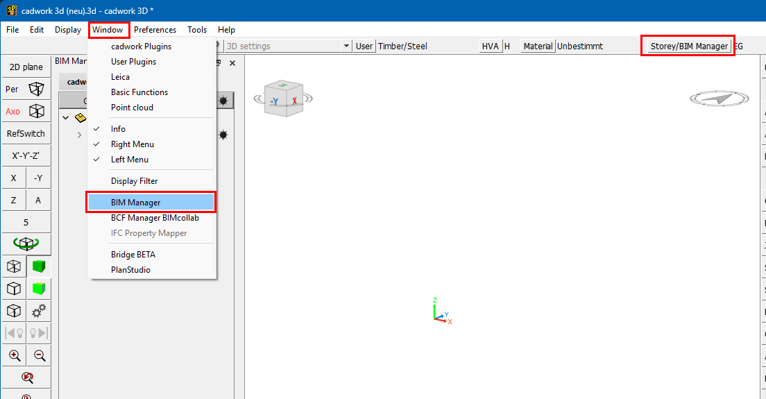
Das BIM Management Tool (BMT), ermöglicht uns ein einfaches Handling im Umgang mit IFC und der BIM Methode. Es kann über die Befehlszeile: → oder mit Klick auf den Button aufgerufen werden. Rechts neben dem Button ist das jeweils aktive Geschoss vermerkt. In diesem Fall werden alle Elemente welche ich hinzufüge dem Geschoss EG hinzugefügt.
Struktur des 3D im BMT
Wir widmen uns im ersten Schritt der Struktur des 3D im BMT.
Im ersten Reiter des BMT ist jeweils der Inhalt der 3D Datei ersichtlich. Mit Maustaste aktiviere ich das Gebäude bzw. das Geschoss. Das aktive Geschoss wird Fett hervorgehoben!
Tipp:
Geschosse oder Gebäude können nur gelöscht werden, wenn keine Elemente diesen zugewiesen sind. Ebenfalls wird mindestens ein Gebäude mit Geschoss behalten!
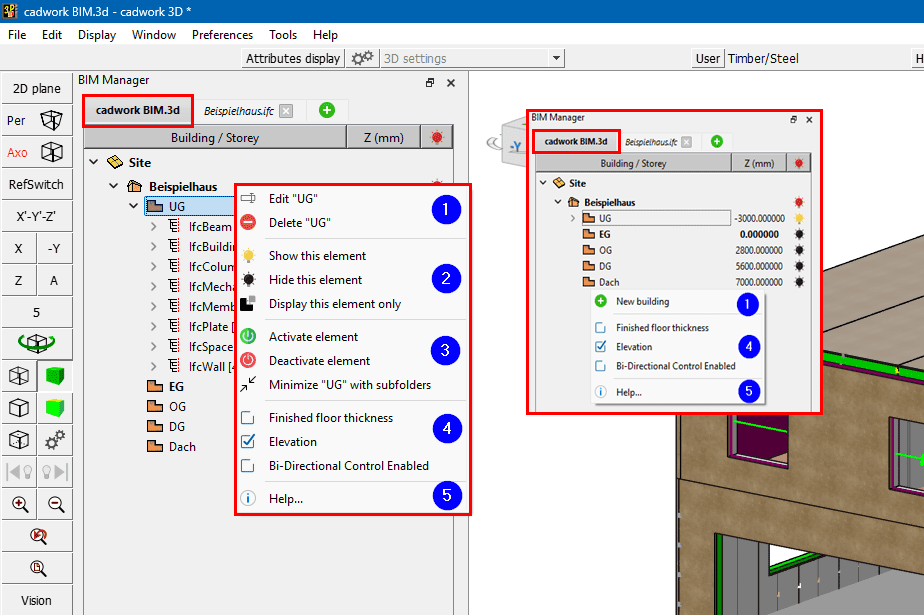
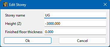
1 Editieren Geschoss bzw. Neues Gebäude/Geschoss hinzufügen.
2 Sichtbarkeiten, ein und ausblenden von Elementen. Funktioniert auch nach IFC-Typ Aktivieren, Treeview
3 Durch das Anwählen der Schaltflächen Elemente aktivieren, oder Elemente deaktivieren, kann der Zustand der Elemente gesteuert werden. Minimieren bzw. Maximieren des Treeview.
4 Geschossinformationen anzeigen
Hier kann ausgewählt werden ob Informationen wie Fussbodenstärke und Geschosshöhe eingeblendet werden soll. Mit "Nur eins anzeigen" wird die Sichtbarkeit auf ein Geschoss beschränkt.
5 Aufruf zum 3D BIM Manual
Tipp:
Bi-direktionale Aktivierung springt jeweils zu dem momentan aktiven Bauteil im 3D.
Bereich der IFC Datei
Nun bewegen wir uns im Bereich der IFC Datei
Tipp:
Mit der IFC Lizenz ist es möglich ein IFC einzulesen. Mit der Lizenz "BIM-Manager" können mehrere IFC-Dateien gleichzeitig eingelesen werden.
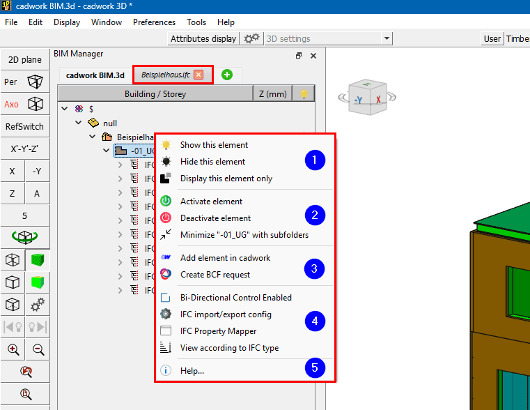
Durch das Anwählen der Schaltflächen Elemente aktivieren, oder Elemente deaktivieren, kann der Zustand der Elemente gesteuert werden.
Minimieren bzw. Maximieren des Treeview.
Elemente aus importierten IFC-Dateien werden als "Exchange" Elemente angezeigt und können zu cadwork Elementen konvertiert werden. Somit können diese für die Planung weitergenutzt werden (z.B. als Referenzbauteile). Durch Klicken auf als Bauteil erzeugen, werden die selektierten Elemente zu cadwork Bauteilen konvertiert. In der Struktur des IFC werden diese ausgegraut und der Struktur im 3D hinzugefügt.
Bi-direktionale Aktivierung springt jeweils zu dem momentan aktiven Bauteil im 3D.
IFC-Importeinstellungen vornehmen und anpassen.
IFC Property Manager mit dem Attribute aus der IFC-Struktur gemappt werden können.
Ansicht nach Typ ermöglicht das Umstellen der Anzeige im BMT nach IFC-Typ oder nach der IFC-Hierarchie
Tipp:
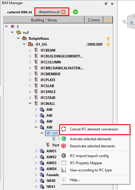
Als Bauteil erzeugte (konvertierte) IFC-Elemente können im BMT in den IFC Dateien annulliert werden.
Wichtig:
Prüfen Sie den Inhalt der erhaltenen Daten immer zuerst in einem Viewer (QualityGate), anschliessend sind die importierten Daten in cadwork sorgfältig auf ihre Richtigkeit (Genauigkeit, Informationen) zu kontrollieren
IFC Viewer:
Liste verschiedener Viewer
Die Konvertierung kann über → vorgenommen werden, oder über das Kontext Menü im BMT. Gültige Elemente werden nach ausführen der Konvertierung zu cadwork Elementen umgewandelt. Ungültige Elemente können nicht zu nativen cadwork Elementen konvertiert werden. Ungültig heisst, wenn z.B. die Geometrie inkorrekt beschrieben ist. Kontrollieren Sie die Daten sorgfältig auf ihre Richtigkeit (Genauigkeit, Informationen).