2.5 IFC Import-Einstellungen
Der Dialog zu den Importeinstellungen kann über das BMT aufgerufen werden oder über:
Exportieren → Datei → Zahnradsymbol IFC-Datei
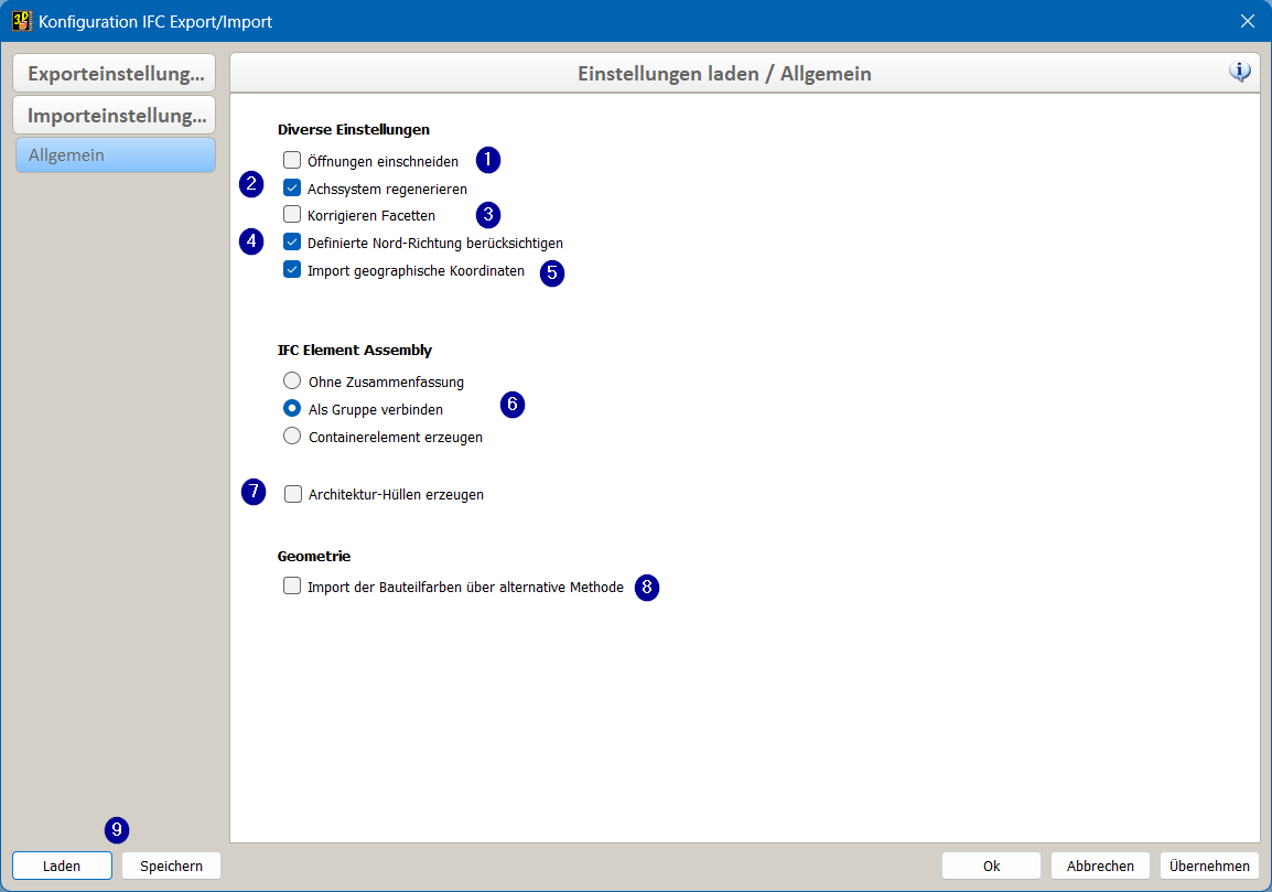
IFC Import-Einstellungen
1 Öffnungen einschneiden
Definiert ob Öffnungen nach dem Import hart/weich eingeschnitten werden sollen, oder ob das IfcOpeningElement zu einem Element mit dem Typ Öffnung generiert werden soll.
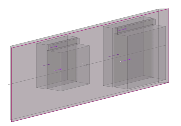
Wand mit Fensteröffnungen.
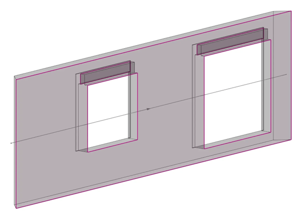
Wand mit eingeschnittene Fensteröffnungen.
Tipp:
In Verbindung mit dem Elementbaumodul muss diese Funktion deaktiviert sein!
2 Achssystem regenerieren
Das Achssystem der Elemente wird algorithmisch neu berechnet und ausgerichtet.
3 Korrigieren Facetten
Facetten, die auf einer Ebene liegen, werden, wenn möglich korrigiert.
Kann zu längeren Importzeiten führen!
4 Definierte Nord-Richtung berücksichtigen
Import der Richtung des "wahren Nordens" (True North), oder der geografischen Nordrichtung in Bezug auf das zugrunde liegende Projektkoordinatensystem.
Achtung:
Die definierte Projektrotation muss zwingend beibehalten werden. Das Modell darf nicht händisch an rotiert werden. Wollen Sie gemäss X- / Y- Achsen arbeiten ist die temporäre Nullpunktrotation oder die temporäre Cursorrotation zu bevorzugen!
5 Import geographische Koordinaten
Import der Längen-, Breitengrade sowie der Bezugshöhe (Elevation) in die Projektdaten.
6 IFC Element Assembly
Die IfcElementAssembly repräsentiert Elementbaugruppen, die aus mehreren Elementen zusammengesetzt sind. z.B. Fachwerkbinder, Stahlträger und verschiedene Arten von Rahmen, können durch die Entität IfcElementAssembly dargestellt werden. Durch Auswahl der Buttons kann definiert werden ob das IfcElementAssembly in cadwork Ohne Zusammenfassungen, als Gruppe verbinden (empfohlen) oder mit einem Containerelement erzeugt werden soll.
7 Architekturhüllen erzeugen Hier kann gesteuert werden ob die Exchangeelemente (linkes Bild) in konvertierte Elemente mit Hüllkörper (rechtes Bild) umgewandelt werden sollen oder nicht. Grundsätzlich empfiehlt sich diese Einstellung.
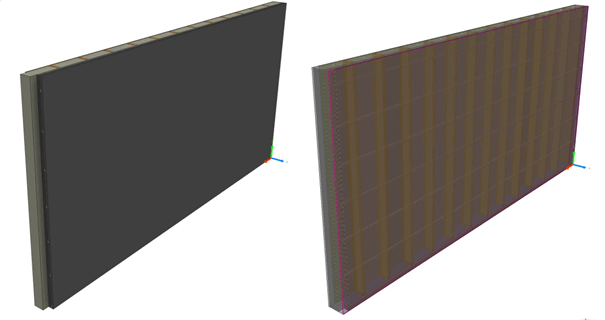
Links wurde keine Architekturhülle erzeugt. / Rechts wurde eine Architekturhülle erzeugt.
8 Geometrie
In IFC-Dateien werden Farben durch RGB-Werte mit einer sehr großen Anzahl von Farbmöglichkeiten beschrieben, die nur zufällig genau den 256 in cadwork zur Verfügung stehenden Farben entsprechen. In der Regel werden Bauteilfarben aus der IFC-Datei über den cadwork Import eingelesen, mit dem die erkannten RGB-Farben automatisch in eine möglichst passende cadwork-Farbe konvertiert wird. Manche Modelle werden in Viewern dennoch in einer anderen Farbe dargestellt, als sie später im cadwork konvertiert werden. In diesen Fällen können Sie - falls die Farbe für die Konstruktion entscheidend ist - die Farben über einen alternativen Konverter erzeugen lassen, der in manchen Situationen eher die angezeigten Farben übernimmt. Sollte die Konvertierung im ersten Schritt nicht den Vorgaben entsprechen, aktivieren Sie diese Option "Import der Bauteilfarben über alternative Methode" und importieren die Bauteile erneut.
9 Laden und Speichern von Einstellungen
Grundsätzlich empfiehlt sich die Standardeinstellungen in der INIT-Datei abzuspeichern. Je nach Bedarf ist es möglich die Einstellungen separat abzuspeichernd zu laden.